
Compressed Air Storage and Distribution (Energy Engineering)
Abstract
Consistent stable operation of an industrial compressed air system is achieved when compressed air flow supplied to the system equals compressed air demand. Energy distributed to the system is available from two sources; rotating energy of the air compressors, and energy from compressed air storage. Optimum system energy efficiency is possible when the proper amount of energy is available from compressed air storage. Presented here are the physical and mathematical relationships that may be used to assess system performance and determine compressed air storage requirements. These relationships are also applied to design the air storage volume and distribution pressure profile necessary for effective compressed air storage.
INTRODUCTION
Compressed air systems have historically used on-line air compressor capacity sufficient to supply peak air demands.Where air receivers have been installed, the system’s pressure profile and lack of storage control limit the effectiveness of compressed air energy storage. Today’s energy costs and competitive world economy require that inefficient, wasteful practices of the past must end. This entry develops the necessary calculations to assess compressed air energy demand and calculate the usable compressed air energy in a properly engineered storage system. Methods of design, application, control, and optimization of compressed air energy storage are introduced.
ENERGY FLOW IN COMPRESSED AIR SYSTEMS
Compressed air systems can be viewed as having two parts: supply and demand. The supply system includes air compressors, dryers, filters, and equipment found in the powerhouse/compressor room. The demand side includes perhaps hundreds of use points, including tools, actuators, process use, blowing, cooling, material transport, and sparging (a process whereby air is injected into a tank of liquid, resulting in a bubbling of the solution to provide a desired action). The amount of energy necessary to drive productive air demands is changing constantly as equipment and processes start and stop. During normal machine cycles, compressed air use is often cyclical rather than continuous.
Normal demand variations and diversity of applications result in an airflow profile with peaks and valleys in airflow rates that are at times significantly more or less than the average air demand. For reliable operation of the system, peak air demands must be supplied as they occur. If air supply falls short of demand, system pressure will decrease. When peak air demands are not supplied, system pressure can fall below the minimum acceptable operating pressure. This often leads to lost productivity.
The supply of air is available from two sources; rotating on-line compressed air generation capacity and compressed air energy storage. Operating excessive air compressor capacity to supply peak airflow is inefficient and expensive. Properly engineered compressed air energy storage will supply peak air demand and reduce rotating on-line energy. The result is improved overall system efficiency and reduced power cost.
Compressed Air Generation Efficiency
Generation efficiency is highest when an air compressor is operating at full-load capacity. It is common for compressors to operate at less than full-load capacity, a condition referred to as part-load operation. During part-load operation, a compressor consumes less than full-load power as its compressed air output is reduced. “Specific power” measured as power per unit of air produced (kW/ 100 scfm), however, is greater during part-load operation. The result is that part-load operation is less efficient than full-load operation. Compressors may also operate in the no-load or unloaded condition. When unloaded, the air compressor produces no compressed air at all yet consumes 25%-30% of full-load power. Running compressors unloaded for a long period greatly reduces a system’s overall generation efficiency.
Compressed Air System Efficiency
Supplying peak airflow demand with rotating on-line generation requires one or more compressors to operate in the part-load or unloaded condition. As the peak demand occurs, the compressor(s) will load for a short time during the demand event and then return to part-load or unloaded operation. The result is poor overall system efficiency.
For a compressed air system to achieve maximum operating efficiency, the compressed air supply should incorporate both compressed air generation and storage. The goal is to supply average air demand with generation (on-line rotating energy) and to supply peak airflow requirements from storage (stored compressed air energy).
Compressed Air System Energy Balance
The energy delivered to and consumed in a compressed air system is a function of the weight or mass flow of air moving through the system. The mass of compressed air depends on pressure and temperature. Increasing pressure increases the density and, therefore, the mass of air. Increasing air temperature will decrease the air’s density, decreasing the mass of air. This relationship is stated in the Ideal Gas Law.[1]
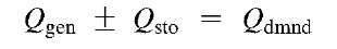
The ideal balance between generation and demand is achieved when Qgen= Qdmnd-
Ideal Air System Energy Balance

Only when system pressure = constant
Eq. 2 Ideal compressed air system energy balance.
The first law of thermodynamics for a change in state of a system,[2] or the law of conservation of energy, states that energy is not created or destroyed. This implies that the airflow rate of generation must equal the airflow rate of demand. From practical experience, it is observed that generation and demand are not always equal, resulting in changing system pressure. When Qgen> Qdmnd> system pressure increases, and when Qgen< Qdmnd, system pressure decreases. The energy imbalance between generation and demand is either absorbed into or released from storage (Qsto).
With Compressed Air Entering and Exiting Storage
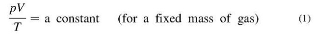
Eq. 1 Ideal Gas Law for fixed mass of gas.
Compressed air is often measured in terms of its volume—ft3, for example. The volumetric measure of air is irrelevant with respect to the air mass unless the temperature and pressure of the air volume are also known. Therefore, standards are adopted to express the mass of air under “Standard” conditions, resulting in the definition for a Standard Cubic Foot of air (scf). Standard conditions adopted by CAGI (Compressed Air and Gas Institute) and Compressed Air Challenge® (CAC) are 14.5 psia, 68°F, and 0% relative humidity.
Compressed air energy transfer can be expressed as the mass flow rate of air at a given operating pressure in standard cubic feet per minute (scfm). This is both a measure of volumetric flow rate and the mass or weight flow rate of compressed air. Higher-flow-rate scfm delivers a higher power rate, and the time duration of flow determines the energy transferred.
Compressed air power enters the system from the air compressors and exits the system through air demands, including productive demand, leaks, and all points where compressed air leaves the system, expanding back into the atmosphere. Power delivered from the compressors is measured as mass flow rate Q (scfm) from generation, or Qgen, and power leaving the system also is measured as mass flow rate of air demand, or Qdmnd.
Definition: Qgea. Airflow rate of generation is the compressed air mass flow rate (scfm) produced by the rotating on-line compressor capacity at any moment.
Definition: Qdmnd. Airflow rate of demand is the compressed air mass flow rate (scfm) escaping from the compressed air system to the atmosphere at any moment.
Entering storage pressure increases Exiting storage pressure decreases (3)
Eq. 3 Actual compressed air system energy balance.
Definition: gsys. Airflow rate of the system is the compressed air mass flow rate (scfm) produced by the rotating on-line compressor capacity (2gen) at any moment, minus the airflow absorbed into storage (— Qsto for increasing pressure) or plus airflow released from storage (+ Qsto for decreasing pressure) (Fig. 1).
Practical Air System Energy Balance
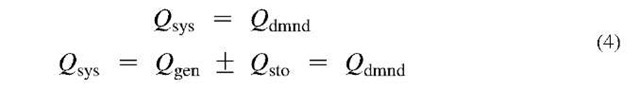
accounts for changing system pressure Eq. 4 Energy balance of compressed air systems.

Fig. 1 Airflow relationship: generation, storage, and system flows.
COMPRESSED AIR ENERGY STORAGE
The compressed air system engineer must analyze the dynamics of compressed air energy storage. This section develops the mathematical expressions necessary to study the relationship among air system generation, storage, and demand. To optimize system operation, system energy supply must remain balanced with air demand. Furthermore, system energy supply must be optimized between generation (rotating on-line energy) and storage (stored compressed air energy).
Application of the Combined Gas Law
The combined gas law states that the pressure of an ideal gas multiplied by volume divided by temperature is a constant.
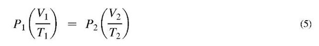
Eq. 5 Combined Gas Law.
The compression process usually begins with air at ambient conditions of pressure and temperature (assuming no moisture content). A larger volume of air is compressed to a reduced volume, increasing the pressure of the air. During the compression process, the air’s temperature increases. Assuming the air’s temperature is ultimately returned to ambient, as a result it can be said that the end pressure of the compression process is equal to the initial pressure times the ratio of beginning volume to ending volume (compression ratio).
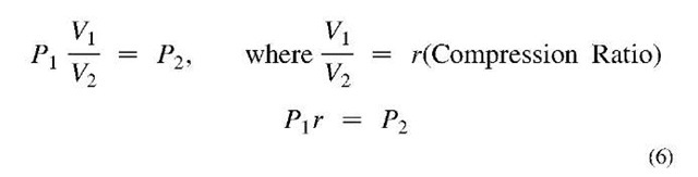
Eq. 6 Compression ratio.
If during compression, 7.9 ft3 of air are reduced to a volume of 1 ft3, the resultant pressure is 7.9 times the initial pressure or the ratio (r = 7.9 times).
Assume that the compressor intakes 7.9 ft of dry atmospheric air at 14.5 psia. Multiplying by r=7.9 results in a pressure of 114.5 psi absolute or 100 psi gauge (Fig. 2).
The application of the combined gas law is the basis of compressed air storage calculation. More advanced forms of the calculation can be used to assess many aspects of compressed air system performance.
If an air receiver of 1 ft3 volume is pressurized to 114.5 psi absolute, and its discharge valve is opened to the atmosphere, how many ft3 of air (at atmosphere) will be discharged from the receiver? The form of the ideal gas law used to solve this problem is

Eq. 7 Gas volume-receiver volume relationship (assuming temperature = constant).

Eq. 8 Gas volume released from a receiver.
In the previous discussion of air compression, it was shown that reaching a pressure of 114.5 psia requires compressing 7.9 ft3 of air. The receiver calculations above, however, show that only — 6.89 ft3 of air are released from the 1 ft3 receiver above.
What happened to the other cubic foot of air? The other cubic foot of air is still inside the air receiver because the receiver’s pressure remains at 14.5 psia (1 atm).

Fig. 2 Compression of air from atmospheric pressure to 100 psi gauge (114.5 psi).

Fig. 3 Air receiver pressure change.
It is important to note that the receiver’s pressure change is the slope of the line calculated from final pressure minus initial pressure. Looking at the receiver pressure throughout time, when pressure is falling (negative slope), air is flowing from the receiver to the system. The xy plot in Fig. 3 shows pressure (y) and time (x). Storage airflow Qsto has an inverse relationship between the storage receiver and system—that is to say, air leaving the receiver (— Qsto) is air entering the system (+ Q sto).
Pneumatic Capacitance
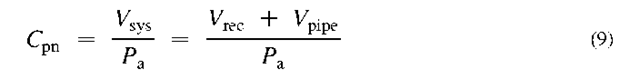
Pneumatic capacitance of a compressed air system (Cpn) represents the compressed air energy absorbed into or released by a compressed air system as its pressure increases or decreases. It is expressed in terms of the mass of air/unit change in pressure—for example, Standard Cubic Foot/Atmosphere (scf/atm) (Table 1).
Eq. 9 Pneumatic capacitance.
For every 1 atm change of system pressure, increase or decrease, the system will absorb or release one times its volume (ft3) of compressed air. Eq. 9 above gives the capacitance of the system in terms of ft3 per atmosphere of pressure. Assume that the atmosphere is at standard conditions of pressure and temperature, and that the piping volume is negligible.
I am text block. Click edit button to change this text. Lorem ipsum dolor sit amet, consectetur adipiscing elit. Ut elit tellus, luctus nec ullamcorper mattis, pulvinar dapibus leo.
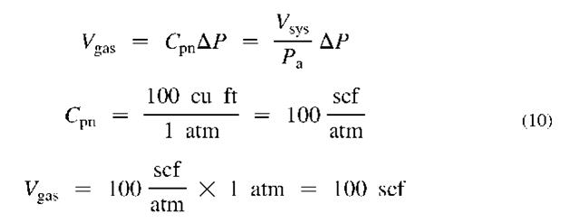
Eq. 10 Volume of gas as a function of pneumatic capacitance (Cpn).
Eq. 10 shows that a 100 ft3-volume air receiver changing pressure y 1 atm will displace 100 scf of air into or out of the vessel. The pneumatic capacitance of the system is 100 scf/atm. If the AP is positive (i.e., initial pressure is lower than the final pressure), the air displaced is 100 scf, and air is absorbed into the air receiver tank. If the AP is negative (i.e., initial pressure is higher than the final pressure), the air displaced (100 scf) is delivered from the air receiver tank.
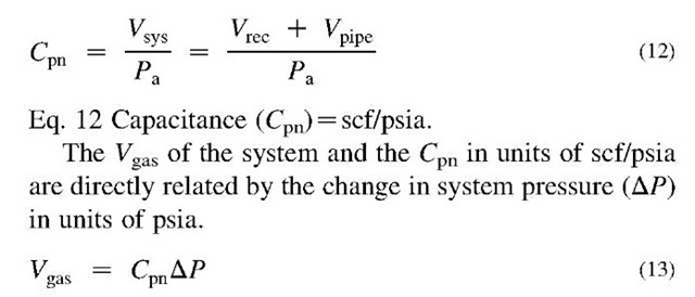
Because compressed air system pressure is often measured in psi, it is desirable to express the capacitance of compressed air systems in terms of scf per psig (scf/psi).
For the system above with Vsys = 100 ft3, the capacitance is 6.896 scf/psia. If the system pressure delta is 14.5 psia (1 atm), the stored Vgas is 100 ft3 (see Eq. 14), because atmosphere (14.5 psia) is the condition defined for Standard Gas Conditions Vgas = 100 scf.

Eq. 11 Capacitance and storage pressure delta (scf/psia).
Therefore, pneumatic capacitance of a compressed air system (Cpn) is a function of the total volume of the system and atmospheric pressure, which can be expressed as:
Air System Pressure Profile and Storage Delta
The highest pressure available in the system is usually determined by the maximum working pressure of the air compressors. The lowest acceptable operating pressure is determined by manufacturing requirements. With an air compressor rated at 125 psig maximum working pressure and a required use-point pressure of 75 psig, for example, a maximum 50 psig pressure differential is available. Only a portion of this differential can be used for storage, as there are unrecoverable pressure losses as compressed airflows through the system. The pressure profile in Fig. 4 allows for 15-psig control pressure band, 5-psig treatment pressure drop, 2-psig loss through distribution piping, and 8-psig differential in the point-of-use connection piping.
Given a minimum demand-side use-point pressure of 75 psig, and including the imposed pressure delta (10 psi) through distribution plus point-of-use piping, the pressure profile in Fig. 4 shows that the lowest optimum target pressure of the supply-side header is 85 psig. The normal supply-side header pressure is 105 psig. This profile allows for primary storage pressure differential of 20 psig available to the system.
There are costs associated with compressed air energy storage. The discharge pressure at air compressors must be increased to provide storage pressure differential. Increased energy is about 1% for each 2-psig increase in compressor discharge pressure (for positive displacement-type compressors). Also, increasing the compressed air system pressure increases the air demand of the system. Compressed air leaves the system through various openings to the atmosphere, such as the open port of a control valve, a blowing nozzle or open blowing tube, or a leak in the piping. Any opening in the system that does not have a pressure regulator controlling the applied pressure will blow an increased amount of airflow as the system’s applied pressure is increased. This increased airflow is called artificial demand. System air demand is increased by approximately 1.0%-1.3% for every 2-psig increase in system pressure. For systems with little effective use-point pressure regulation, artificial demand will be greater.
Definition: Artificial demand. Artificial demand is the additional compressed airflow demand consumed by the system due to actual applied air pressure being greater than the minimum required target pressure.
For the pressure profile shown in Fig. 4, the storage pressure differential is 20-35 psig as compressor controls cycle between their load and unload set points. If the average storage pressure differential is 28 psig, the resulting power increase is 14%, and waste to artificial demand is between 14 and 18% of the system’s airflow.
As shown above, creating compressed air energy storage increases the system’s energy requirement and power cost. Therefore, it is unwise to create more storage than the system requires. Proper design will minimize the increased compressor discharge pressure and power requirement. Also, proper control of compressed air energy in storage can virtually eliminate artificial demand. This topic is discussed in “Maximize and Control Compressed Air Energy Storage,” presented later in this entry.
But first, the compressed air system engineer must consider various system requirements for stored energy and engineer the storage system appropriately. The following sections demonstrate common applications of the pneumatic capacitance calculation to solve various system energy storage requirements.
Calculate Useable Compressed Air in Storage
Compressed air energy in storage is of use to the air system only if storage pressure is greater than the minimum system supply pressure. Given the pressure profile shown in Fig. 4, and assuming that the air receiver volume of the system is 1000 gal, the amount of usable compressed air energy in storage can be calculated.
For an air receiver of 1000-gal volume with 20 psia primary storage delta P, see Fig. 4; solve for the usable compressed air energy storage Vgas (scf) (assuming that the air is at standard temperature and relative humidity).
Eq. 15 Pneumatic capacitance (Cpn) and usable storage ( Vgas).
Calculating Peak Air Demand
During a large demand event, the supply pressure in the system above is observed to draw down from 105 to 80 psig in 30 s. What is the airflow rate for Qsto (scfm) during the demand event?
Adding time to Eq. 12 for gas volume (scf) allows solving for gas flow rate Qsto (scfm).
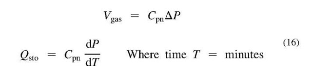
Eq. 16 Solve for storage airflow rate Qsto (scfm).
Solving for the peak airflow rate from storage (Pf, final pressure; Pj, initial pressure),

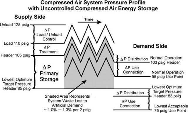
Fig. 4 Compressed air system pressure profile with uncontrolled storage.
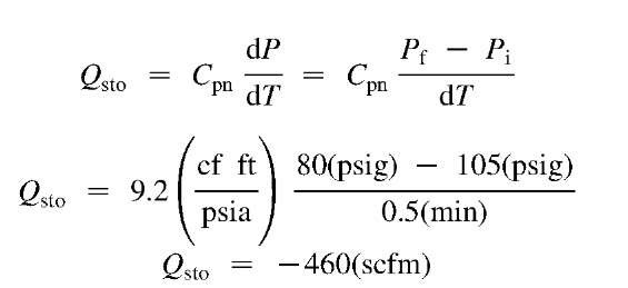
The storage airflow rate is 460 scfm, which is equal to approximately 100 hp of rotating on-line compressor capacity.
Calculating Required Receiver Volume for Demand Events
How much air receiver volume should be added to support the demand event while maintaining supply pressure at 85 psig minimum? Solve Eq. 15 for pneumatic capacitance (Cpn); then convert to gal and solve for additional receiver volume.
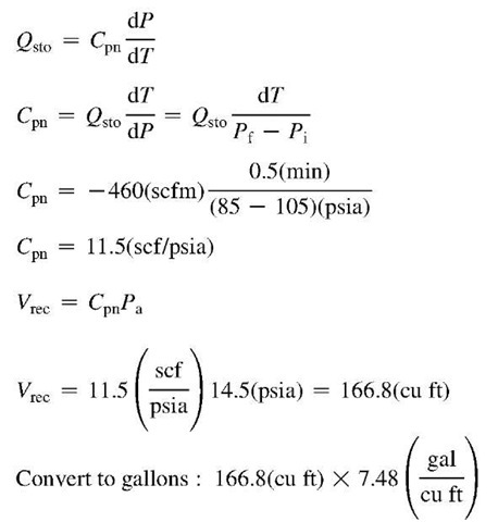
= 1248(gal) Additional Receiver Volume: 1248 – 1000
= 248(gal) (17)
Eq. 17 Solve for additional air receiver volume (gal).
period that might range from many seconds to minutes depending on the type of compressors and controls. Most air compressors must start in an unloaded state to allow the electric motor to accelerate to normal running speed. For a typical lubricant-injected rotary screw compressor with part winding or 7-Delta, for example, starting might require 5-10 s for transition to full running torque. When the permissive time is past, the compressor’s controls must open the inlet to begin compressing air. Then the internal piping, oil sump receiver, and possibly after-cooler must be pressurized before the compressor’s internal pressure exceeds the system pressure and the first cubic foot of air is forced through the compressor’s discharge check valve into the air system.
Consider the air system shown in Fig. 5, including three compressors operating in a baseload, trim capacity, and standby control configuration. The system air demand is 700 scfm required at 85 psig minimum pressure. The base-load and standby compressors are fixed-speed load/unload compressors with rated capacity of 400 scfm. The trim compressor is a variable-speed drive (VSD) compressor rated at 500 scfm capacity. The VSD trim compressor is set to maintain a target pressure of 90 psig. Assume that the standby compressor is set to start automatically at a pressure of 88 psig and requires a 15 s permissive startup time to deliver its first ft3 of air into the system.
With the unanticipated shutdown of the base-load compressor, what size air receiver (gallons) is necessary to ensure that the system pressure does not fall below 85 psig during the permissive startup time of the standby compressor?
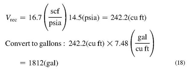
First, calculate the airflow required from storage after shutdown of the base-load compressor. System air demand is 700 scfm with shutdown of the base-load compressor; the VSD trim compressor will increase its air delivery to full capacity of 500 scfm. The remaining air deficit of 200 scfm must be supplied from storage (Qsto). The pressure profile for the event will result in a fall of pressure to 88 psig before the standby compressor is signaled to start. The minimum pressure for the receiver is 85 psig. Therefore, the initial receiver pressure (Pi) is 88 psig, and the final receiver pressure (Pf) is 88 psig. The permissive startup event duration is 15 s or 0.25 min.
Calculating Air Storage for Compressor Permissive Start-up Time
Storage of compressed air energy is also necessary to support compressed air demand during various supply-side events. One common supply-side event is the unanticipated shutdown of an air compressor (due to a motor overload or a high-temperature condition, for example). The startup of reserve compressor capacity requires a

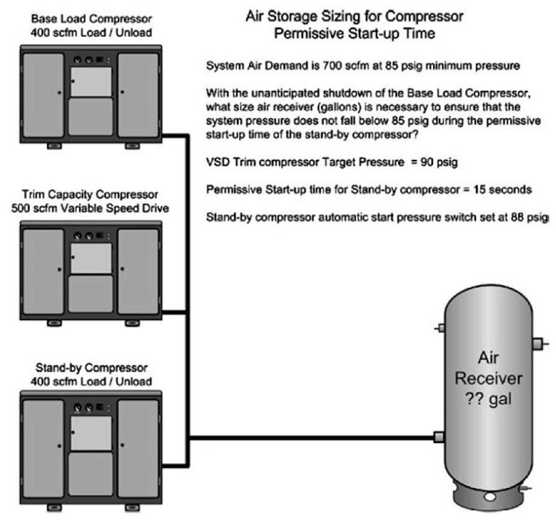
Fig. 5 Base-load, trim capacity, and standby compressed air system.
Eq. 18 Permissive startup—solve for pneumatic capacitance and receiver volume.
Pneumatic capacitance calculations can be applied to solve a variety of compressed air storage requirements.
MAXIMIZE AND CONTROL COMPRESSED AIR ENERGY STORAGE
For compressed air energy in storage to be effective, the storage pressure must be higher than the demand-side target pressure. As supply-side pressure increases, the power required by positive displacement compressors also increases. The air compressor’s power increase is approximately 1% for every 2-psig increase in discharge pressure. Increased storage pressure or increased air receiver volume increases usable air in storage. The economic tradeoff is the capital cost of increased air receiver volume vs the increased compressor supply-side energy cost of higher storage pressure.
Higher pressure also adds energy cost to the system’s air demand. Increasing supply-side pressure creates a corresponding demand-side pressure increase. The result is additional energy consumption of the system through an air system loss called artificial demand. Simply stated, if the compressed air pressure applied to leaks and unregulated air use points is increased, the airflow consumed will also increase. Artificial demand is the additional compressed airflow demand consumed by the system when the actual applied air pressure is higher than the minimum required target pressure. Artificial demand in a system without any effective point-of-use pressure regulation will increase the system’s energy demand by 2% for each 2-psig increase in pressure. In a “typical” compressed air system, it is common to find that 35%-50% of all air demands have effective pressure regulation. Therefore, artificial demand typically increases by 1.0%-1.3% for every 2-psig increase in applied system pressure.
Artificial demand can be eliminated by controlling the demand-side target pressure at an intermediate point separating the supply and demand sides of the system. An intermediate flow control valve is installed as shown in Fig. 6, downstream of the primary storage air receiver at the beginning of the distribution piping. This separates the supply side from the demand side of the system.
Flow control is used to control the energy (airflow) entering the system while maintaining a real-time energy balance between supply and demand. An intermediate flow control is a packaged assembly of one or more flow control valves in a manifold arrangement with an automatic bypass or fail-safe open override device. It is normally installed in the compressor room at the beginning of the main piping distribution system. Adequate-size receiver(s) installed upstream of the flow control provide compressed air energy storage for controlled release into the system. The flow control senses air pressure at its discharge. Changes in the demand-side energy requirements cause fluctuating pressures. The flow control senses these changes and increases or decreases the airflow from storage as needed to maintain the system’s energy balance between supply and demand. The result is stable system pressure set at the lowest optimum target pressure— normally, to within + 1 psi (Fig. 7).
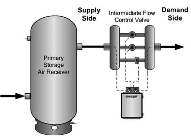
Fig. 6 Intermediate flow control separates supply and demand.
The upstream compressed air energy storage is crucial to the satisfactory application of an intermediate flow control. The valve package responds immediately to the fluctuating pressure, so compressed air energy from storage must be available for instantaneous expansion into the system to maintain the supply/demand energy balance. The immediate energy supply cannot be dependent on rotating on-line generation. Air must be stored during dwells in the demand cycle when excess compressor capacity is available. Then stored energy is released by the intermediate flow control to satisfy the peak demands.
The intermediate flow control, like all components of a compressed air system, has some unrecoverable pressure loss, which represents an energy cost to the system. Intermediate flow controls are designed to operate with low unrecoverable pressure loss—typically, less than 5 psig. For the pressure profile shown in Fig. 6, the intermediate flow control has an unrecoverable pressure loss of 3 psig, which represents 1.5% increased energy cost at the compressor. In Fig. 4, it is shown that waste to artificial demand is between 14 and 18% of the system’s air demand. The net savings achieved by eliminating artificial demand with application of intermediate flow control is 12.5%-16.5% of the system’s energy input.
SUMMARY
Compressed air systems constantly undergo dynamic changes in their energy demand. For reliable, consistent, and efficient system operation, energy supply and demand must be balanced in real-time performance. Operating a system without proper energy storage results in part-load or no-load operation of compressors, which decreases system efficiency and increases energy cost.
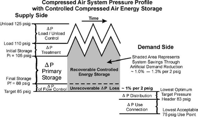
Fig. 7 Compressed air system pressure profile with controlled storage.
Compressed air energy storage can provide the necessary energy to meet peak demands. Pneumatic capacitance calculations derived from the Ideal Gas Law and First Law of Thermodynamics for systems allow mathematical modeling of compressed air energy storage. Usable air storage is a function of two factors: available storage volume, and the pressure difference between storage pressure and demand-side target pressure.
Demand-side target pressure should be the lowest optimum pressure required to support productive air demands. Increasing storage pressure increases the compressor’s energy use by 1% per 2 psig. Uncontrolled compressed air storage pressure also increases the applied demand-side pressure, resulting in waste to artificial demand. Artificial demand typically wastes 1.0%-1.3% of the system’s airflow for every 2-psig increase in system pressure.
Artificial demand can be eliminated through the application of intermediate flow control to separate supply and demand. The intermediate flow control paces the energy flow from supply to demand, maintaining a real-time energy balance. The result is reliable, consistent, and stable operation at an appropriate demand-side target pressure.
CONCLUSION
The compressed air system engineer must assess the dynamic energy characteristics of the air system. Compressed air energy storage requirements to support normal system events must be calculated. Energy storage must be optimized with an appropriate system pressure profile allowing the necessary storage pressure differential and adequate air receiver storage volume. Proper control of stored energy and the resultant control response of the system’s air compressors, when optimized, will provide the best possible system operating efficiency.

